Desktop Lathe
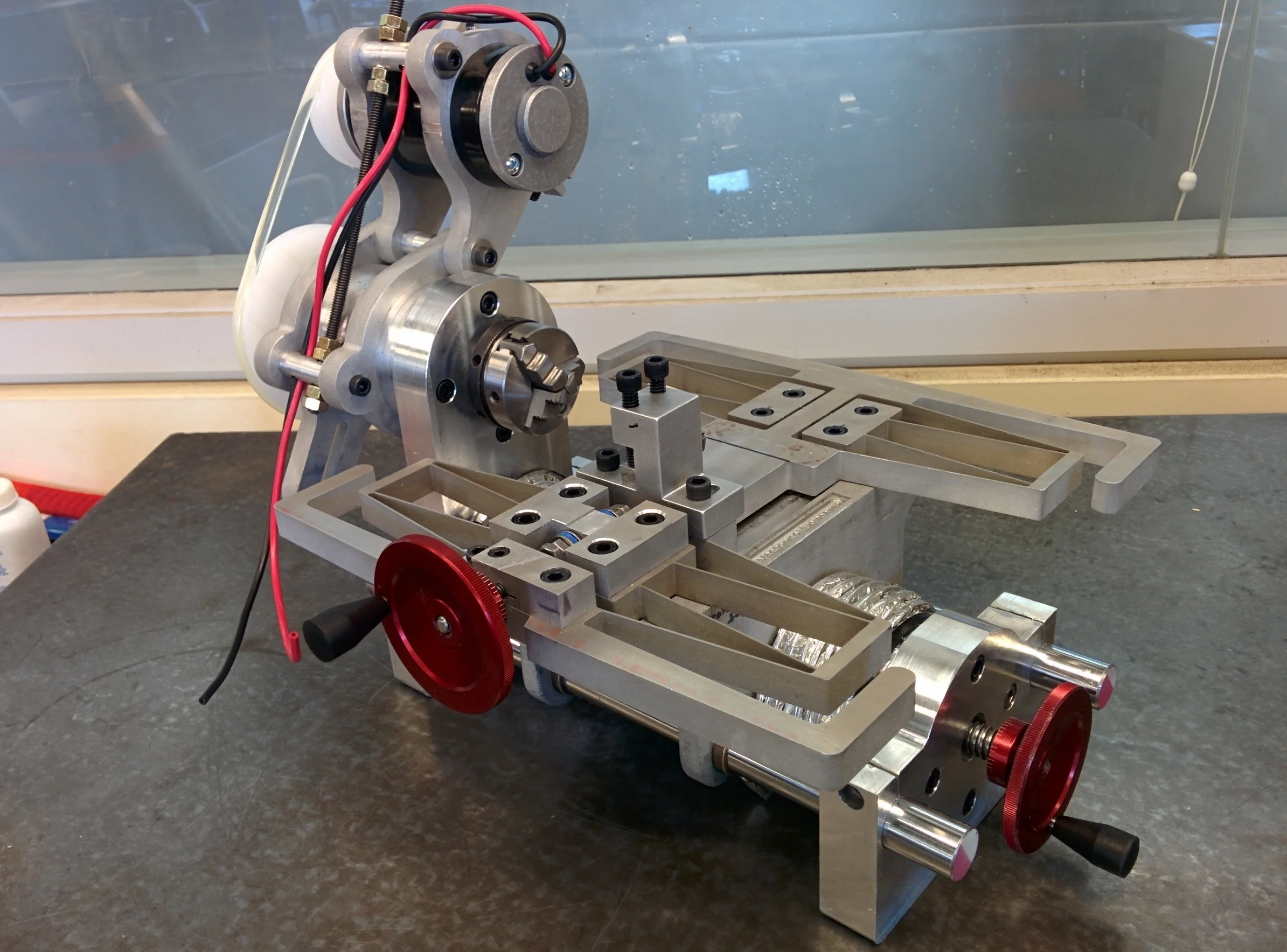
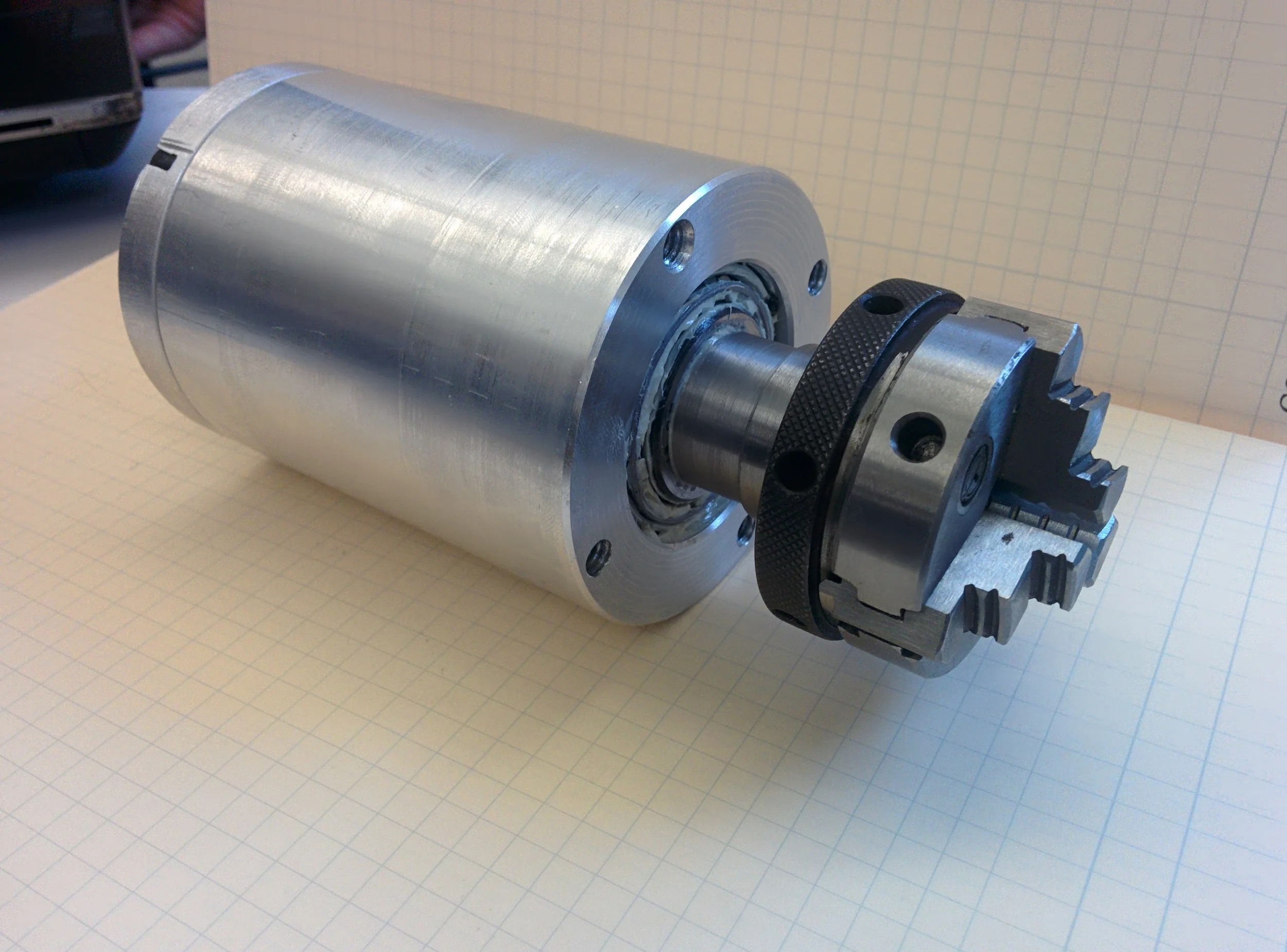
In 2.72 - Elements of Mechanical Design, my team was charged with designing, building, and testing a desktop lathe capable of cutting a 0.5" aluminum rod within a tolerance of +/- 0.002". To meet this main requirement, we first had to create mathematical error models in MATLAB to parameterize how the design of certain parts would affect the overall error. Using applied mechanics, this provided an understanding from which decisions about individual part design could be made. CAD models and FEA were used extensively to verify part stiffnesses, deflections, and stresses. By the end of the semester, we were able to deliver a well-designed, built, and tested machine that performed within specifications. Our lathe survived the required drop test and performed the best out of 6 other undergraduate teams.
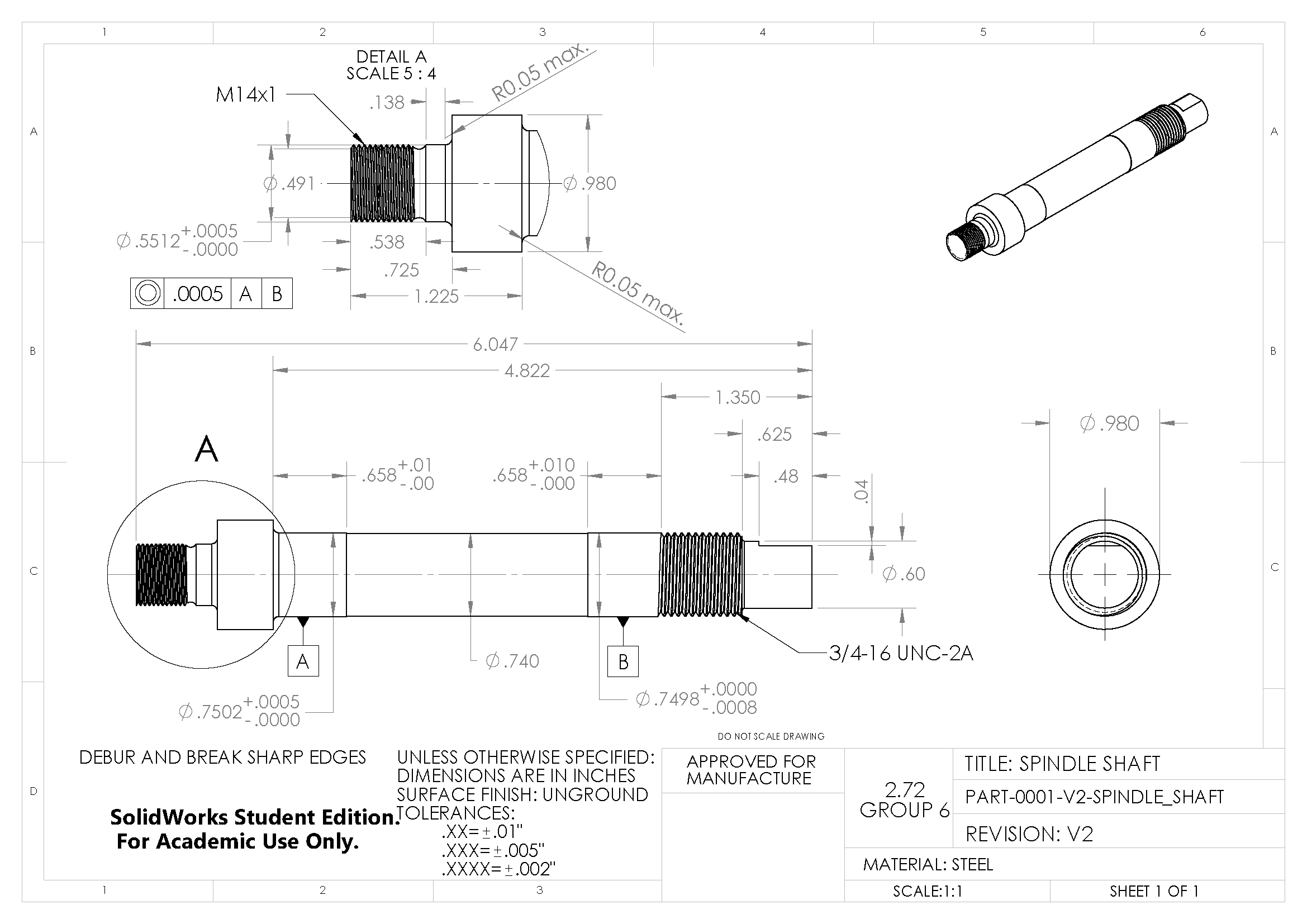
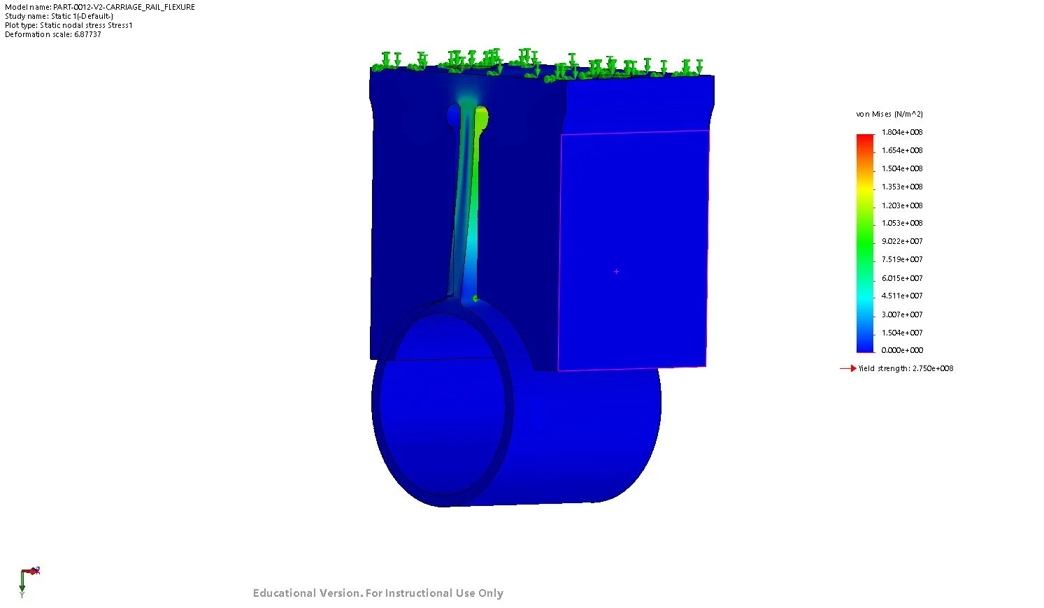
As a CAD/FEA lead on the team, my main responsibilities were designing the lathe's various flexures, ensuring proper integration of parts in CAD, and creating engineering drawings for manufacturing. Through working with the modeling leads on my team, I guided design decisions and ensured that these design decisions had the desired effect on manufacturability and ease of assembly. I was extensively involved with flexures design, most of which were used to ensure that parts/subassemblies were not overconstrained in the final lathe assembly. This consisted of using FEA to iterate through flexure designs with the goal of obtaining desired allowable deflections while maintaining acceptable stresses.


